Frequency Converter for Pumps
PUMP BASICS
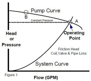
The affinity laws apply to pumps as they do to fans. To understand frequency converter applications applied to pumps, it is a good idea to review the basics of how pumps are applied in general. Figure 1 shows a pump curve relative to a hydronic system curve. The pump curve describes the head (or pressure) versus flow characteristics of a particular pump. The curve shows that the pump will produce limited flow , at point B, if it is applied to a system with a large differential pressure required to lift the water/glycol and overcome resistance to flow. Larger flow rates are achieved with this pump if pressure differential is reduced- as at point A. To determine where along the pump curve the pump will operate requires information provided by the system curve. The system curve show the characteristics of the piping system. It shows the friction head as it increases with flow. Friction head is the measure of resistance to flow provided by the pipe, valves, elbows and other system components.
STATIC HEAD
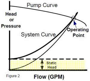
The head required at zero flow is a called static head or lift. Figure 2 shows the combined friction and static head curve for the system. The static head is the amount of feet of elevation the pump must lift the water regardless of flow. Another way to look at is as the work needed to overcome gravity. The intersection of the pump and system curves shows the natural or design operating point for the system. At this point pump pressure matches system losses. The intersection would generally be chosen to ensure that the pump is operating at or near its best efficiency.
FLOW CONTROL
TWO WAY CONTROL VALVES:
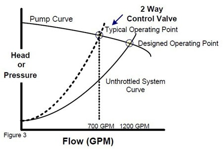
Most hydronic systems do not always work at design conditions. Systems with 2-way control valves vary the flow by modulating the valve to various positions. Closing the valve reduces flow and increases system friction in the system. Figure 3 shows a typical operating point when a particular flow is achieved by the control valve. Notice that the flow is achieved but at a increased system pressure.
Three way control valve systems maintain constant pressure by bypassing flow from pump discharge to the pump suction. While good flow is maintained, pump flow and energy consumption is also maintained no energy savings. (Figure 1)
PUMP ENERGY SAVINGS WITH FREQUENCY CONVERTERS
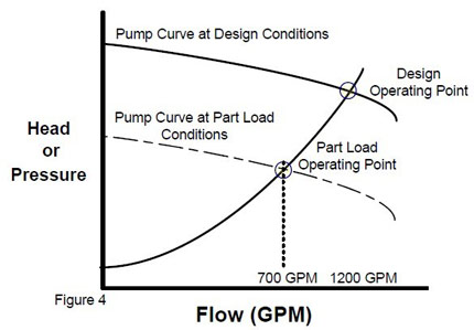
Applying a frequency converter to a pump to reduce speed and therefore flow, causes the pump curve to shift down as shown in figure 4. Since the operating point is still the new reduced pump curve and the system curve, the same reduced flow (note 700 GPM from 1200 GPM in figures) is achieved as with a valve. This flow is achieved but at a reduced pressure. Operating at reduced pressures can result in longer pump seal life, reduced impeller wear and less system vibration and noise. Due to the affinity laws, power is greatly reduced at reduced flows thus offering significant savings by frequency converter.
Typical Pump Applications with Frequency Converters
- Chilled and Hot water Pumps
- Condenser Water Pumps
- Booster Pumps
APPLYING FREQUENCY CONVERTERS TO PUMPS To REALIZE SAVINGS
After reconst
As with most HVAC systems, original pump designs may be based on worst case maximum flow conditions for future expansion reasons, or the designer used the usual 15 to 20% over-sizing criteria. When evaluating frequency converter retrofit opportunities for energy savings, one should look the system and pump curves and review the existing method of modulating the flow. (see figure 1)
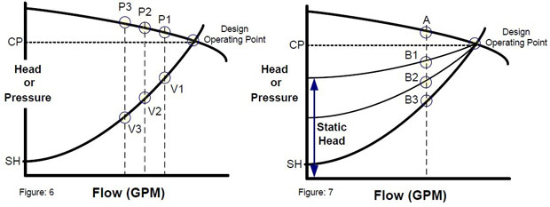
BYPASS: If bypass control is used (example: 3-way valve at coils ) the frequency converter system is always at constant pressure.(See CP in Figure 6). The savings potential can be quite large if there is no modulation present when frequency converters are retrofitted.
2-Way VALVE CONTROL: If 2-way valves are used, the system operates along the pump curve from Operating Point to P3. These systems use less energy than constant pressure systems.
If a frequency converter is being applied, the system will operate along the system curve from Operating Point to V3.
ruction, damper opening is 100%, which reduces resistance loss a lot. Because motor runs in variable frequency, fixed resonance frequency is difficult to be line with operation frequency, thereby resonance can be avoided. So problem of pipeline breakage is solved naturally. This is also an unexpected benefit.
STATIC HEAD
Static Head can affect possible energy savings. If static head is high, the system curve can approach constant pressure. For example, in Figure 7, a pump curve is shown with three system curves one with no static head, and two others different static heads. For a given flow rate, the difference between points A and B represent possible energy savings. Basically, the lower the static head, the greater the energy savings that can be achieved with frequency converters.
DETERMINING PUMP & SYSTEM CURVES
Pump curves are readily available from pump manufacturers, however, system curves are more difficult to determine. One quick method can approximate the curve:
- Determine the un-throttled (open) system flow rate at the location under consideration. (you may need to measure this at different locations or have a balancer establish this for you)
- Measure the static head
- Plot these two points on a copy of the pump curve.
- Connect these points using a square function: Head = Flow2
P1, P2, P3 = Outlet Valve Flow Positions
V1. V2, V3 = Frequency Converter Operating Points
SH = Static Head
CP = Constant Pressure
